
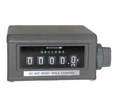
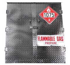

Propane 101
In order to properly size the RegO® Regulator, find the total load of the installation. The total load is calculated by adding up the input ratings (BTU or CFH) of all appliances in the installation. Input ratings may be obtained from the nameplates on the appliances or from the manufacturers' literature.
| TYPE OF SYSTEM | MAXIMUM LOAD | Suggested Regulator |
|---|---|---|
| First Stage in a Two Stage System | 1,500,000 | LV3403TR |
| 2,500,000 | LV4403SR Series LV4403TR Series |
|
| Second Stage in a Two Stage System | 450,000 | LV3403B Series |
| 935,000 | LV4403B Series | |
| 1,600,000 | LV5503B4/B6 | |
| 2,300,000 | LV5503B8 | |
| 9,800,000 | LV6503B Series | |
| Second Stage in a 2 PSIG System | 1,000,000 | LV4403Y4/Y46R |
| 2,200,000 | LV5503Y6/Y8 | |
| Integral Twin Stage | 450,000 | LV404B34/39 Series |
| 525,000 | LV404B4/B9 Series | |
| 800,000 | LV404Y9 | |
| Automatic Changeover | 200,000 | 7525B34 |
| 450,000 | 7525B4 |
Determine the type of regulation needed referring to the chart below.
Now determine which regulator in the Series would be most suitable. Turn to the individual product pages and refer to the Performance Curves. Check the performance of the regulator with your actual load conditions at the minimum LP-Gas inlet pressure for the regulator. Use the pressure corresponding to your lowest winter temperatures shown in the chart below or refer to the delivery pressure of your first stage regulator.
| TEMPERATURE | APPROX. PRESSURE (PSIG) | ||
|---|---|---|---|
| °F | °C | PROPANE | BUTANE |
| -40 | -40 | 3.6 | NA |
| -30 | -34 | 8 | NA |
| -20 | -29 | 13.5 | NA |
| -10 | -23 | 23.3 | NA |
| 0 | -18 | 28 | NA |
| 10 | -12 | 37 | NA |
| 20 | -7 | 47 | NA |
| 30 | -1 | 58 | NA |
| 40 | 4 | 72 | 3.0 |
| 50 | 10 | 86 | 6.9 |
| 60 | 16 | 102 | 12 |
| 70 | 21 | 127 | 17 |
| 80 | 27 | 140 | 23 |
| 90 | 32 | 165 | 29 |
| 100 | 38 | 196 | 36 |
| 110 | 43 | 220 | 45 |
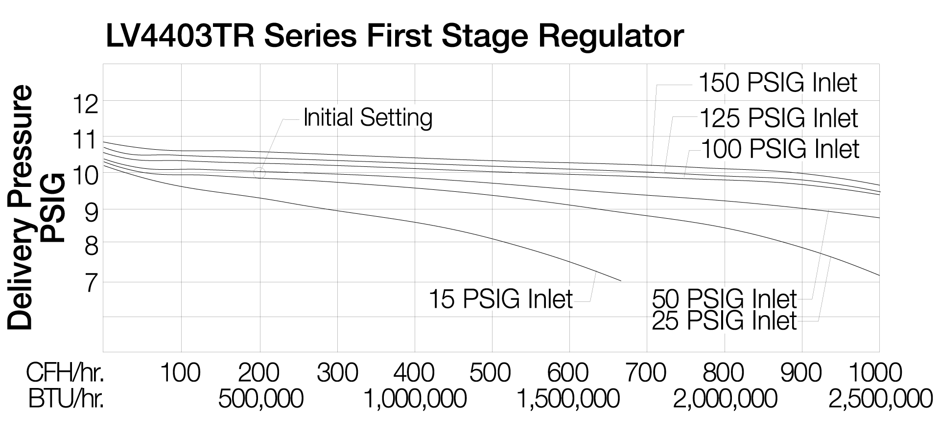
Example for a First Stage Regulator
- Assume a load of 500,000 BTU's per hour.
- Assume a minimum delivery pressure of 9.5 PSIG.
- Assume a minimum tank pressure of 15 PSIG.
- For these conditions, refer to chart for the LV4403TR Series, First Stage Regulator, shown below.
- Find the line on the chart corresponding to the lowest anticipated winter tank pressure (note that each performance line corresponds to and is marked with a different inlet pressure in PSIG).
- Draw a vertical line upward from the point of assumed load (500,000 BTU's per hour) to intersect with the line corresponding to the lowest tank pressure.
- Read horizontally from the intersection of these lines to the delivery pressure at the left side of the chart. In this example the delivery pressure will be 9.7 PSIG. Since the delivery pressure will be 9.7 PSIG at the maximum load conditions and lowest anticipated tank pressure, the regulator will be sized properly for the demand.
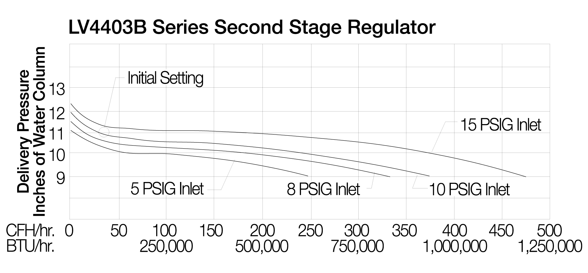
Example for a Second Stage Regulator
- Assume load of 250,000 BTU's per hour.
- Assume a minimum delivery pressure of 10" w.c.
- Assume a minimum inlet pressure of 10 PSIG.
- For these conditions, refer to chart for the LV4403B Series, Second Stage Regulator, shown below.
- Find the line on the chart corresponding to the anticipated inlet pressure.
- Draw a vertical line upward from the point of assumed load (250,000 BTU's per hour) to intersect with the line corresponding to the lowest inlet pressure.
- Read horizontally from the intersection of these lines to the delivery pressure at the left side of the chart. In this example the delivery pressure will read 10.6" w.c. Since the delivery pressure will be 10.6" w.c. at the maximum load condition and lowest anticipated inlet pressure, the regulator is sized properly for the demand.